Column internals
Bio-Energy Carbon Capture & Storage in CHP plants will result in negative CO2 emissions in the future
Today, there are many development projects around the world aimed to find effective carbon capture and storage (CCS) technologies and this is highly relevant also for CHP plants. Combined heat and power plants fuelled by biomass and using carbon capture of flue gases is one of the few technologies today that leads to a negative CO2-emission footprint. This technology is known as Bio-Energy Carbon Capture and Storage (BECCS).

How is it possible to achieve negative CO2 emissions?
The simplest way to explain it is that when biomass grows, it absorbs carbon dioxide from the atmosphere. When the biomass is burned in the CHP plant, the carbon dioxide is captured using BECCS technology. The captured carbon dioxide is then stored in deep geological formations, removing it from the natural carbon cycle.
This is how BECCS can be designed at a CHP plant:
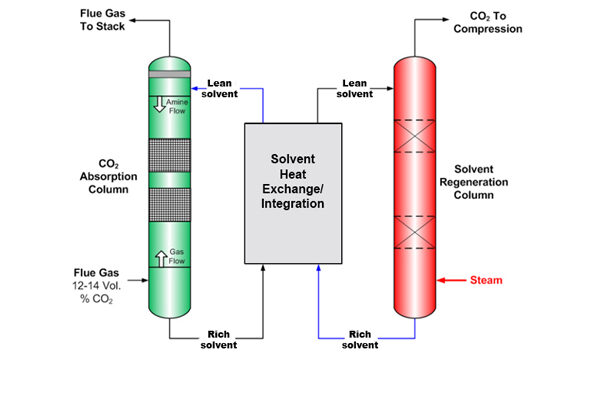
1. Gas pre-treatment – If particles/aerosols or sulphur dioxide are present in the flue gases, the gases need to be pre-treated and then cooled before they are fed into an absorption column. In a CHP plant, the flue gas can fulfil these requirements after the flue gas condensation step if the condensing column is optimally designed.
2. CO2 Absorption – The CO2-rich flue gas is fed into the bottom of an absorption column, where the carbon dioxide in the flue gas reacts with and is absorbed by a downward flowing solvent.
3. Desorption/Regeneration – The CO2-rich solvent from the absorption column is passed to the top of a desorber/regeneration column, where the liquid flows downwards countercurrent to vapour flowing up the column. Carbon dioxide is removed from the solution at this stage. Pure carbon dioxide leaves the top of the desorber, where it then goes on to be processed and liquefied.
4. Carbon dioxide storage – The captured and liquefied carbon dioxide is transported to be stored, for example, under the seabed.